Simple cutoff switch for 3-pin? CRV driving me crazy

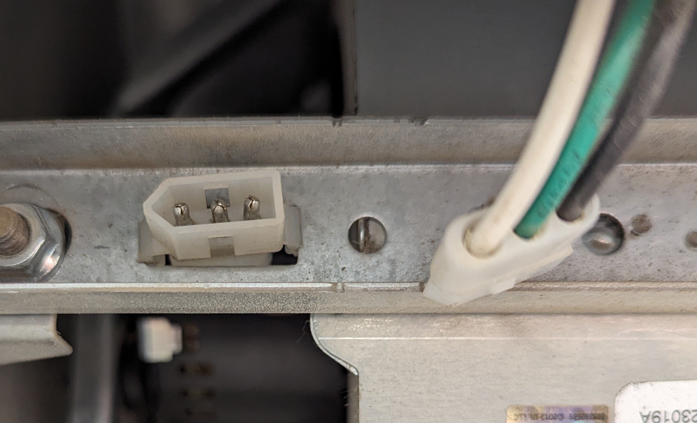
I’m looking to install some cutoff switch on this 3-pin connector. It almost looks like a PC 4-pin 12v connector, but it actually connects to a Broan CRV motor. Specific model is the L150L.

I originally wanted a ventilator with a timer, but they installed an inline CRV (intake only) with a crazy 150CFM for a tiny 480sqft suite. Massively overkill, and loud. I’d prefer to put this on a timer, or even better would be a smart switch control. But at the very least a manual switch would be great.

For now, and for the last two years, I just have this unplugged, as shown in the image. The passive ventilation on the connected ducting has been more than enough to turn the air around. But sometimes it’d prefer to enable the intake for a time. I just can’t have it on all the time because the air turnaround is nutty, not to mention the blast of cold air in the middle of winter.

Any ideas for a switch that fits this connector, or a DIY switch, and/or something to hook to a timer, OR smart switch somehow?

Syldon,
@Syldon@feddit.uk avatar

If you are still looking to fix this search for a 3 pole switch. This link states 60w of power, so a rocker switch should be fine.

Be careful and check the rocker internal before you buy. Some state 3 core and use a pass over method for the earthing wire.

https://feddit.uk/pictrs/image/cb4df1fc-4345-4970-9154-6c1881ba0fb1.png

Wiitigo,

Oh man. Thanks for the info. And the confirmation that the motor is still 120v low amp.

Since it’s 120, rather than the rocker switch (great idea, and thanks for the links) do you think it’s possible to wire up my spare Lutron switch?

https://lemmy.world/pictrs/image/cd4fd57a-5e41-4915-add6-8e7fd241540d.jpeg

I just wouldn’t know which wires of the switch map to the wires in line to the motor…

Syldon,
@Syldon@feddit.uk avatar

Last week I installed a 3 pole fan switch for the bathroom extractor to over ride the dodgy humidity sensor it has. It gets turned it on and off manually now. I have a replacement fan ready to install, but I need to cut out 3mm of glass to get it to fit. I am going to wait for the summer in case the worst happens and the glass shatters. This is why I could answer what you needed.

This is similar to the switch I used with a 25mm box to mount it. You can buy a metal mounting box, if you want to bury the fitting.

I prefer a fixed placement box over the loose cable of a rocker switch. Some of the rocker switches have poor cable retention systems, which can result in the cable coming loose over time. Moreso when using thicker cabling. I don’t mind rockers for lighting, but for fixed hardware, its not my first choice, and tbf a rocker switch doesn’t look very nice if it is on permanent display.

I wouldn’t wire up a dimmer switch to a motor. It can cause the motor to stall between poles, which can result in a component becoming hot.

Low-voltage lowdown. For an electric motor, torque changes as the square of the voltage applied. A 10% increase in voltage, for example, will boost torque 21% (1.1×1.1=1.21). Conversely, at 90% of rated voltage, the motor suffers a 19% reduction in torque (0.9×0.9=0.81). A more severe undervoltage condition, 20% below rated value, would reduce the motors torque to only 64% of rating (0.8×0.8 =.64). The effects are a 156% overload and catastrophic failure.

If torque decreases below the torque required by the load, the motor would stall. At that point, the only product of the motor is heat. However, a 100-hp motor, with locked rotor, becomes a 500kW resistive heater.

Fig. 2. Insulation life is halved for every 10°C rise in temperature. In this example, insulation life drops from four years to less than six weeks for a 50°C change in temperature.

Excess heat is a problem for motors because insulation life is halved for every 10°C increase in temperature (Fig. 2). At the same time, the temperature of the winding will rise 10°C to 15°C for each 10% drop in voltage. That means the insulation life of a motor that operates on 10% lower voltage will decrease to only 50% to 75% of its expected life.

Undervoltage events that last long enough to increase winding temperature cause irrevocable damage to winding insulation and unexpected failures later. A sustained low-voltage event can damage the insulation system of every electric motor running during the event. The only motor that’s safe during a prolonged undervoltage event is one that’s turned off.

www.ecmweb.com

Syldon,
@Syldon@feddit.uk avatar

As for how to wire, breaker switches do not have a positive and negative connections. They only either connect or break the circuit. Obviously the wiring has to lead to each corresponding cable (positive to positive).

The earth is critical on devices that have metal shrouds. The earth should be continuous. You can do that by either wiring both earth connections into one side of the switch so it is not ever broken, or by adding a wire cable connection and tucking it safely inside the mounting box…

whosdadog,

It looks like a 3 pin molex connector www.amazon.com/…/B0046ZI9H6

You can use something like this to add wifi control. HiLetgo ESP8266 5V WiFi Relay Module TOI APP Control for Smart Home Automation System www.amazon.com/dp/B071LMSLRW

Tylerdurdon,

Similar to what the other guy said, but what you want to do is determine which lead can be disabled by itself and just cut and solder a switch on that wire. If you can use a small flathead, you may be able to get one of those pins to unsnap so you can test various pins and see which will have the desired effect, then hook up a switch there.

If you want to be cheap and don’t feel like soldering, you can just get a light switch from the hardware store for $4 and use the built in screws.

chemical_cutthroat,
@chemical_cutthroat@lemmy.world avatar

Disclosure: I don’t know what I’m talking about.

I’d imagine the easiest way would be to keep the connector connected, but clip the wires and solder a switch further up the line.

Changetheview,

I’m not a pro either, but I agree.

OP, is that just a 110V AC input line? It looks like it. If so, I think you could splice in just about any 110V AC switch before the connector, then just leave it connected to the device.

Most AC switches will be made for mounted wall use in the usual wall box (like what you use to turn on lights/outlets), but you can find a box that surrounds the whole switch (usually made for outdoor use). Or you can find inline feed-through switches, like this one: a.co/d/5X0WZol

Or you could even wire in a Bluetooth smart switch if you want to get fancy. Quick search led me to this: a.co/d/jkZ9pvo

Make sure the switch can handle the amps pulled. But other than that, it should be pretty simple to add a switch before the connector if that’s a 110V AC line coming in. Not much different than any other switch, just perhaps that it’s not wall mounted.

oo1, (edited )

https://www.broan-nutone.com/getmedia/fd840029-f968-4f1a-877a-04ebe8ac0702/Specs-Sheet-L100L-L150L-en_CA.pdf?ext=.pdf

This datasheet suggests 1.3 amps at 120V 60hz
for <100W power so pretty much any 2A+ mains rated switch should be okay,
the 6A one linked above should be fine.

You could get a mans rated relay with a low voltage control switch for now,
Then add an arduino or something if you feel like a bit more control, and a bit more diy and don't want to go down the mobile phone/ bluetooth/ techpocalypse road.
https://mechatrofice.com/arduino/relay-module-interface

also non pro - but maybe that's all you get on a diy forum.

Wiitigo, (edited )

I was curious about the amperage as well. I mean, I didn’t think they’d be allowed to keep it at 120v at the 3-pin connector, so was thinking they stepped it down somewhere.

So, obviously I’ve no idea what I’m talking about, but if it is drawing 1.3A from 120V, is it possible it’s converted to 13A at 12V prior to this connector to the motor?

If so, I wasn’t sure if a regular wall switch would work. But pretty great if a smart switch like Caseta would, since I already have some in the home.

Edit: Looking at the motor itself, as a replacement part, the sticker does say 120v. So I guess the dinky plastic connector is fine due to the low amperage.

oo1,

i think they don't want to run high current through motors, as that means thick wires, and a much bigger armature and overall motor.

its the current that generates the heat and needs beefy connectors and wires.

There's plenty of mass produced mains rated motors, like most domestic floor / desk / ceiling fans vaccuum cleaners and so on.

oo1,

a commercial controller like this: quite expensive, and way over-rated i think.
https://www.united-automation.com/product/vac2-15e/

cheap ebay equivalent - not sure i'd trust such a thing in my house if used long-term.
https://www.ebay.co.uk/itm/304808637300?hash=item46f802b374:g:hawAAOSw8C5j7zEg

sorry for UK / 240v links - similar stuff for North America/ 120V - will be available and probably cheaper i'd guess.

they'd be pretty simple to wire in following the data sheets.

as others have said, you can snip the connector - leaving plenty of wire each side of the snip - and splice in longer wires to reach the controller, maybe use wago lever connectors for easy modifications later if needed.

  • All
  • Subscribed
  • Moderated
  • Favorites
  • diy@lemmy.world
  • DreamBathrooms
  • ethstaker
  • osvaldo12
  • magazineikmin
  • cubers
  • rosin
  • mdbf
  • Youngstown
  • Durango
  • slotface
  • everett
  • kavyap
  • InstantRegret
  • thenastyranch
  • anitta
  • tacticalgear
  • provamag3
  • cisconetworking
  • modclub
  • GTA5RPClips
  • khanakhh
  • ngwrru68w68
  • tester
  • megavids
  • Leos
  • normalnudes
  • JUstTest
  • lostlight
  • All magazines