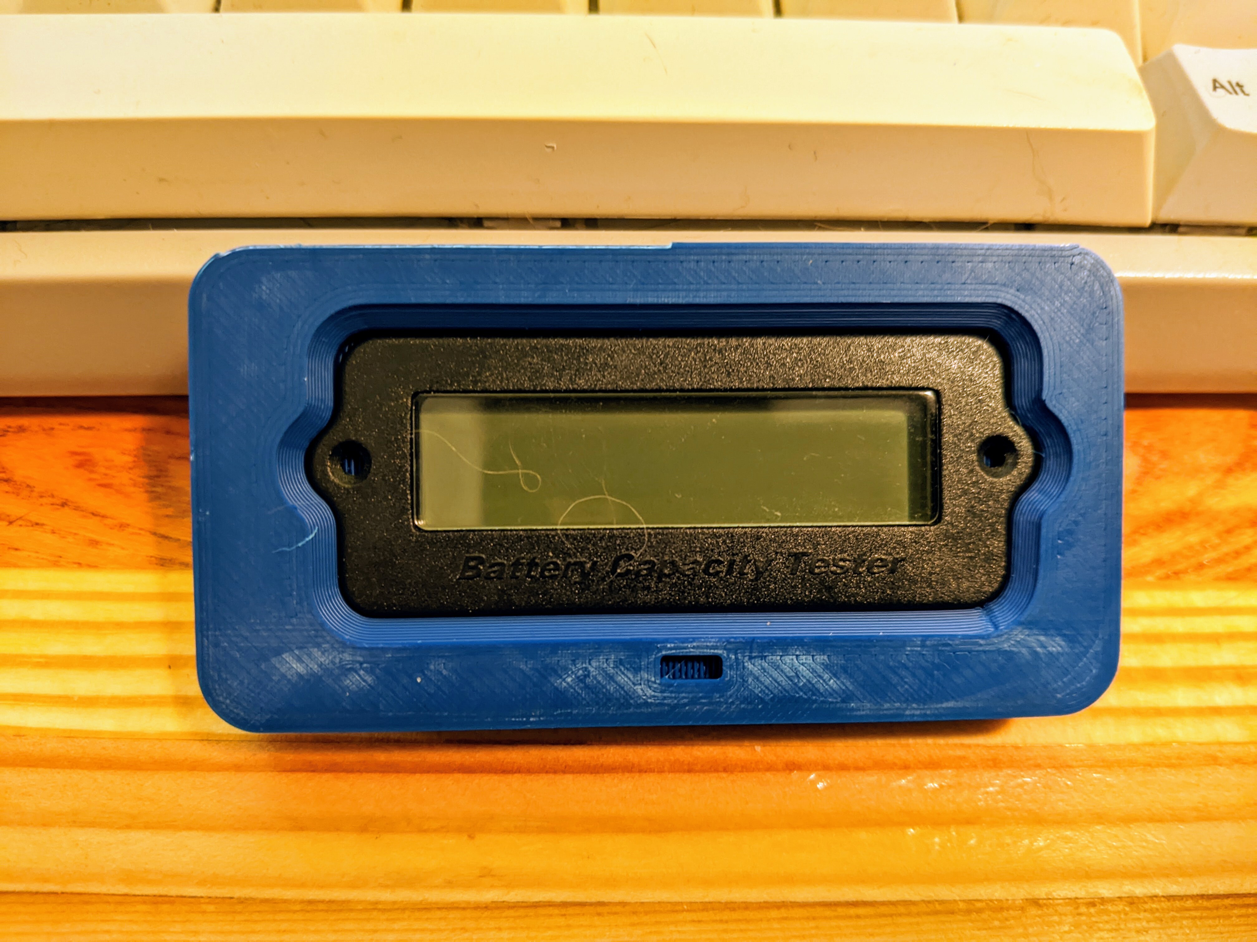
It fits!

Pardon the brim remnants. Not pictured: the many prior iterations. This started as a head on photo that I imported into fusion 360 and scaled after some measuring with calipers. It’s not perfect, but it’s rapidly approaching good enough. The square indent is to help with orientation - although the part obviously is not symmetrical, it’s much harder to judge the home.

Sphks,
@Sphks@lemmy.dbzer0.com avatar

Congratulations ! I usually make 4 or 5 iterations too for each piece, with my least favorite color (toilet paper pink that looked fuchsia on the website). I even launch a print and during the printing I correct my model based on the n-2 print.

Excrubulent, (edited )
@Excrubulent@slrpnk.net avatar

So are you saying you traced a photo, then printed multiple parts to get a trial-and-error fit? And you’re trying to fit the blue part around the black part?

That seems extremely time consuming and wasteful. 3d printing lets you work this way but you’ll get better results by planning out the part more carefully from the start.

The way I would do it is to identify the key measurements. This looks like a complex shape but it can be easily broken down into a few numbers.

First you obviously need the height, width and depth of the main rectangle. Then you need the screw hole diameter. From there, you can measure the distance from the screw hole border to the edge of the tabs that surround the screw hole, and use that to calculate the radius of that whole tab piece. These are all easy with calipers.

From there, there are tricks you can use to measure the corner fillet radius and the internal fillet radius where the screw tabs meet the main body, but also they look like they could be the same as the screw tab radius.

An important piece of info here is that those compound curves are usually just simple circular radii. They’re easy to work with so designers will stick with them.

Try that and see if it looks right. If not, try whole-millimeter adjustments in the numbers till they look the same as your reference part. If you can’t get it right that way, go to half-millimeter increments. People working in CAD software very rarely go to finer adjustments than that for superficial details like this, so it’s usually easy to find the numbers they used.

Then you add a margin between the inner part and the part you’re making, like say 1mm or even 0.5mm, and see if that looks right.

Then all that’s left is to decide whatever measurements you need out of the piece you’re making and go for it.

If you learn to set these parameters up in your CAD software you can easily adjust them until the part looks right.

IMALlama,

I appreciate the reply. You described my usual process, but the dimensions on this thing are very not-round.

So are you saying you traced a photo, then printed multiple parts to get a trial-and-error fit? And you’re trying to fit the blue part around the black part?

Yup!

That seems extremely time consuming and wasteful. 3d printing lets you work this way but you’ll get better results by planning out the part more carefully from the start.

For simpler shapes, I agree with you. That’s exactly what I do usually and I’m pretty good at getting things on the first shot with a pair of calipers and a radius gauge. I do not have convex radius gauges, but I guess I could have printed some. This thing has… very arbitrary dimensions (it’s 23.22mm tall on a pair of mitutoyo calipers - I doubt I’m off by the 0.03 to make it a nice round 23.25). Even if it really does have 0.25mm dimensions, that would make me want to avoid guessing radii. I also wasn’t sure how to guess at locating the bump out for the screw holes accurately. In either case, I would be iterating a few times to get a snug fit.

they look like they could be the same as the screw tab radius.

They’re not :(

An important piece of info here is that those compound curves are usually just simple circular radii

They are!

People working in CAD software very rarely go to finer adjustments than that for superficial details like this, so it’s usually easy to find the numbers they used.

Normally I agree with this, but the dimensions on this part are super goofy. I’ve seen this on a few other random China parts, but it is pretty uncommon.

That seems extremely time consuming and wasteful. 3d printing lets you work this way but you’ll get better results by planning out the part more carefully from the start.

I figured I would have to iterate either way and suspect I did less iterating this way than trying to guess radii. The time commitment wasn’t that large, and would have been similar in either case. As for plastic, each test piece weighs 10 grams and I went through four total, including this one. Nearly all my prints are functional, or they’re fixing broken kid toys (I guess this is functional too), so I’m not too worried about the small amount of waste.

Excrubulent,
@Excrubulent@slrpnk.net avatar

Oh wow, that is very strange. I checked if 23.22mm was anything in inches, and it’s 0.914 and change, so it’s not an imperial thing. I wonder if it just comes from people eyeballing it with no real dimensions or something?

Well, as you were I guess. ¯_(ツ)_/¯

IMALlama,

I appreciate the detailed reply! If anything, someone reading it will learn something. It’s always amusing trying to make nice fitting sockets for random electrical parts. Sometimes the dimensions make a lot of sense. Other times they feel very random, which is surprising given that basically all these parts are probably modeled in CAD.

Excrubulent,
@Excrubulent@slrpnk.net avatar

I appreciate you not being defensive and just explaining your process in so much detail. I learned something about how finnicky some of these parts can be. I wonder if another strategy would be to trace the part onto paper and scan it, to get an undistorted shape?

And I don’t mind explaining things, it’s someting I sort of can’t help to be honest. I hope it’s useful to someone.

IMALlama,

Tracing can work, but it’s a little fickle too. In this case the part had a small radius on its face. There’s also the whole pencil lead has width thing, but it can work OK if you’re very intentional at keeping the pencil tip pointing at the part in question.

Flatbed scanners also work fairly well, but they’re focused at the glass height and you quickly lose detail if the parts have a radius on them.

remotelove, (edited )

The mold was likely 24mm. There could be some shrinkage or a the shot of plastic was a bit light for that set.

Or, it was actually 23.22mm and the dimensions were calculated from another reference point, like PCB or LCD size. If anything, .22mm was supposed to be .25mm clearance.

Translating CAD into plastic and back into CAD can be a very strange thing sometimes.

Edit: I reverse engneer a ton of things in CAD. Sometimes just some calipers work, but for curves, pictures + calipers + gauges are the way to go. Sometimes, if you get core dimensions correct, the correct curves can “emerge” from the design itself, but that is a somewhat rare dark art. Pro-tip: A reverse engineered part is almost never going to be perfect, but almost always has the potential to be better than the original.

j4k3,
@j4k3@lemmy.ml avatar

Why aren’t you printing with PETG and a textured sheet for this? You would get the same surface finish quality as that original bezel.

What are you aligning with orientation?

IMALlama,

This is a test print in ASA in my least favorite color. The current plan is for the ends to be black PETG and the center section to be natural (white ish) ASA. The PETG will be on a textured sheet, this is just laziness in action while making sure the part dimensions were accurate.

Kolanaki,
@Kolanaki@yiffit.net avatar

Whatchya makin?

IMALlama,

Another 3D printed Bluetooth speaker. This is a generic battery level gauge. It’s not completely accurate, but it does a fairly good job of indicating general charge level.

Rather than print the whole face, I cut off just the mount for the screen to iterate. All my other plugs and jacks fit on their first attempt, which was a first. The rocker switch even had a nice satisfying click when it locked into place.

Hopefully I can wrap up CAD in the next week or so as time allows. Everything is done aside from the built in handle.

  • All
  • Subscribed
  • Moderated
  • Favorites
  • 3dprinting@lemmy.world
  • DreamBathrooms
  • magazineikmin
  • mdbf
  • InstantRegret
  • rosin
  • Youngstown
  • slotface
  • love
  • Durango
  • kavyap
  • everett
  • tacticalgear
  • thenastyranch
  • cisconetworking
  • provamag3
  • Leos
  • modclub
  • khanakhh
  • ethstaker
  • osvaldo12
  • GTA5RPClips
  • ngwrru68w68
  • anitta
  • tester
  • cubers
  • normalnudes
  • megavids
  • JUstTest
  • All magazines